Model SC2444
24 to 44 GHz Frequency Converter

The module is designed to interface directly with software defined radios, such as those commonly implemented using Analog Device’s Mixed-Signal Front-End (MxFE), or similar Software Defined Radio, to obtain a complete mmWave system.
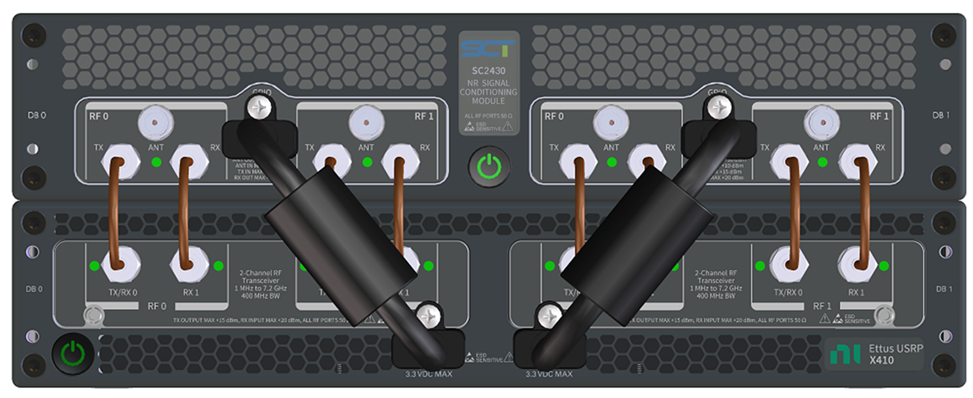
Up to four modules can be combined in parallel to create complex MIMO applications.
Typical Applications
- 5G NR Frequency Range 2 Development
- Software Defined Radio Applications
- Aerospace and Defense
- Advanced Wireless Communications Research
Control of the module is provided via the USB, UART, or SPI interfaces. Most users will find it convenient to control the module using the console interface over USB. Alternatively, embedded controllers may access the UART or SPI interfaces available on the external Control Ports.
Two API protocols are available. The first is ASCII-based, and its commands follow the SCPI structure as defined in IEEE 488.2. The second is a binary protocol, targeted at embedded control applications where speed and timing are critical. Both protocols are detailed in an API Specification.
Up to 4 units can be combined in a vertical stack to create a complex 4 x 4 MIMO radio system. In this scenario, the internal control buses are routed to the cascaded modules over the Expansion Port. In this manner, API commands sent on the primary unit, can be redirected to the downstream modules. This eliminates the need for multiple controllers and simplifies timing and synchronization between units. Module addresses are set using a DIP switch on the Configuration Port.
Secondary and External Controls Port are also available. These ports expose Power, SPI, I2C, UART and GPIO that provide users with a convenient method of interfacing to external front-end modules, such as integrated antenna arrays or switched filter banks.
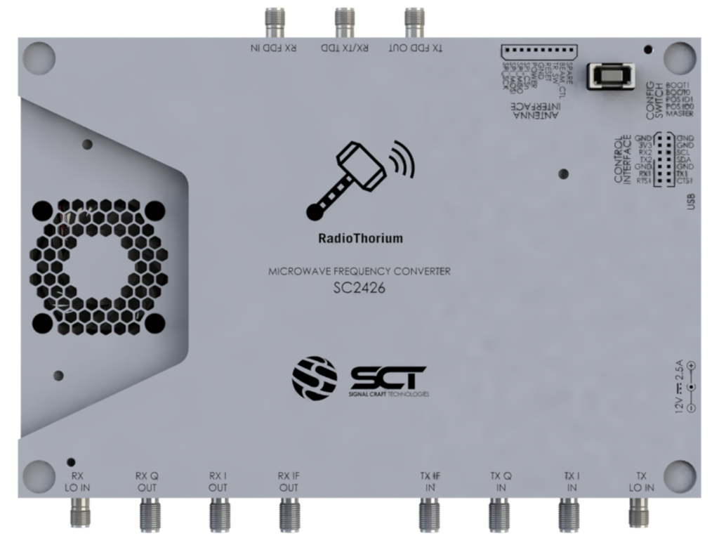
The low-frequency RF inputs include the IF, I/Q, external LO, and external frequency reference ports on SMA connectors.
The converters can be configured to interface with either IF or I/Q signals. The IF port supports signals between 2 and 6 GHz. The I/Q inputs provide connectivity to external single-ended DACs operating at up to 6 GHz. A low pass filter is included to help with alias and spurious rejection.
RadioThorium can be used in either Time Division Duplex (TDD) or Frequency Division Duplex (FDD) mode. The mmWave ports include 2.4 mm connectors for the FDD TX and RX functions, in addition to a bidirectional TDD port.
In FDD Mode, the Up-Conversion (UC) path has approximately 30 dB of gain and an output compression point, or P1dB, of 18 dBm at 40 GHz. In TDD mode, the gain is also 30 dB, but the P1dB reduces to 16 dBm at 40 GHz.
In FDD Mode, the Down-Conversion (DC) path has a maximum gain of approximately 70 dB, noise figure of 10 dB, and an input compression point, or P1dB, of 0 dBm at 40 GHz. In TDD mode, the gain is also close to 70 dB with a noise figure of 12 dB, and an input P1dB of better than 0 dBm at 40 GHz.
Two on-board Local Oscillators (LOs) are provided to facilitate standalone operation. Each LO can be configured independent of the other, providing users with complete control of the RF/LO/IF frequency plan specific to their application.
Optionally, the onboard synthesizers can be disabled when external LOs are supplied by the user.
Upconverter Path

Downconverter Path
Local Oscillators

IF Filter Bank

The following resources are available to registered users:
SC2444 Product Brief
SC2444 Product Specification
SC2444 Getting Started Guide
SC2444 API Specification
SC2444 Mechanical Drawing
SC2444 Letter of Volatility
SC2444 Theory of Operation
Sign In or Create Free Account