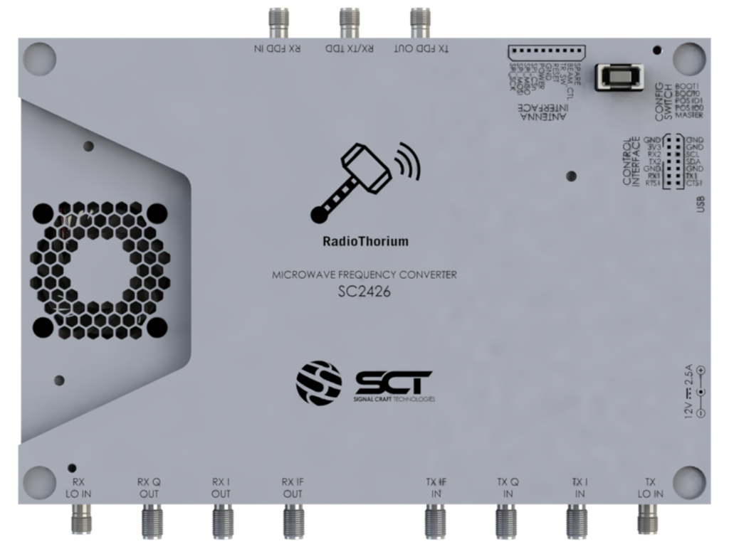
Description
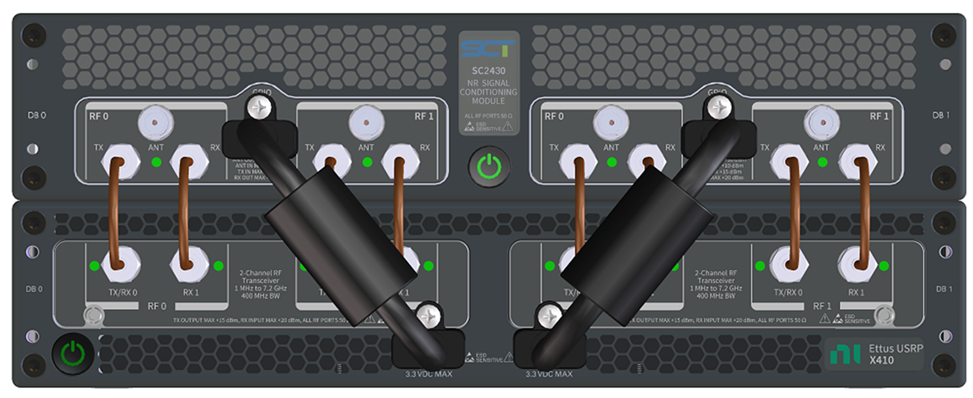
The SC2430 SCM houses two front-end (FE) modules. Each module incorporates two independent pairs of transmit (Tx) and receive (Rx) channels in a Time Division Duplex (TDD) configuration. For applications requiring Frequency Division Duplex (FDD) operation, one radio channel can be configured as a continuous Transmit path and the second as a continuous Receive path.
In summary, the SC2430 can simultaneously support 4 TDD or 2 FDD channels.
The channels incorporate signal conditioning and amplification blocks in both the Tx and Rx path that align with several 5G NR frequency bands (n34, n38, n39, n40, n41, n46, n47, n48, n77, n78, n79, n90, and n96). In addition, bypass paths are available for applications operating outside of these bands.
RF Connectivity to the SDR is established via 8 SMA connectors. The Tx and Rx ports are AC coupled and support signals in the 350 MHz to 7.125 GHz range. The channels provide instantaneous bandwidths (IBW) of 100 MHz (350 MHz to 600 MHz), 200 MHz (600 MHz to 800 MHz), and 400 MHz (800 MHz to 7.125 GHz).
The transmit path can generate 34 dB of gain at 1.9 GHz and 30 dB at 3.5 GHz. Peak output power (P1dB) is approximately 27 dBm and the third order intercept point (OIP3) is 41 dBm. The noise figure is typically 8 dB or better across all frequencies at maximum gain. Band filtering can provide over 50 dB of out of band rejection.
In the receive path, 27 dB of gain is available at 1.9 GHz and 23 dB at 3.5 GHz. Noise figure ranges from 4 dB (1.9 GHz) to 7 dB (3.5 GHz). The input third order compression point is -5 dBm (1.9 GHz) to -1 dBm (3.5 GHz). The unit can survive a maximum no-damage input power +10 dBm. Two banks of 5G NR specific band filters are incorporated into the design, providing over 50 dB of out of band rejection.
The control interfaces are digital ports that the user accesses to configure and program the SCM. Two control options are possible.
The first is an SPI-based interface combined with other GPIO that are presented on the front panel HDMI connectors. SPI signaling is present on pins 1, 4, 6, 7, and 9. The remaining pins are used for GND, Automatic Transmit/Receive or ATR (pins 10, 12), and attenuator latching (13, 15). The ATR and latching pins are provided to facilitate high speed TDD operation as defined in the 5G specification. The SPI port can operate at 40 MHz for write and 16 MHz clocks on read functions.
Users of the NI Ettus-USRP X410 SDR will likely prefer this control option. Like other USRP compatible hardware, the SC2430 can be setup as a UHD device and controlled through the X410. The SC2430 driver is compatible with the UHD Extension Framework. When the SC2430 Extension is enabled, X410 configuration will include SCM performance. For example, setting X410 gain will result in X410 and SCM gain settings that are optimum for the current operating conditions.
Standard HDMI cables can be used for the interconnection. Alternatively, short, mechanical locking cables are available from SCT. These cables incorporate chokes to minimize emissions. A separate interface is provided for each module.
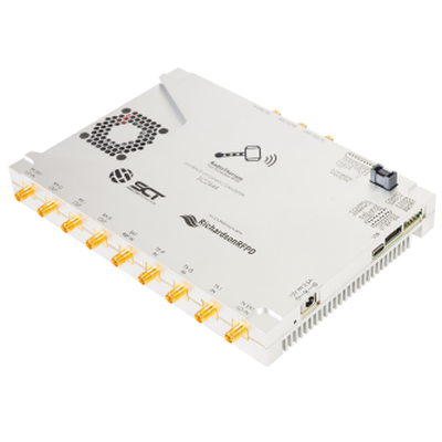
A second control option provides users access to the SC2430 via a UART console interface on the USB-C connector at the rear of the chassis. The USB port is required during firmware updates in the field.
A full API specification is available on the support page of SCT’s website, https://www.signalcraft.com/support.
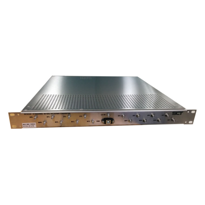
The external power input requires a 12 VDC, 16 Amp, supply. A universal AC/DC power brick is included with the SC2430. Other compatible supplies can be used if high density or rack mounted operation is desired. The SC2430 can be powered on via the front panel pushbutton or set to auto-start on application of the 12-volt input. The front panel pushbutton also serves as indicator for the SC2430 power status.
On the front panel, the SC2430 is equipped with one LED per channel to indicate its status (Transmitting or Receiving).

